Blog
4 Sep 2025
Ballistic protection for military land vehicles – challenges and solutions
Modern military land vehicles are exposed to a range of threats that go well beyond conventional ballistic attacks. These include kinetic energy projectiles (KE threats), shaped charges, improvised explosive devices (IEDs) and mines, as well as new types of threat such as top-attack weapons including loitering munitions, cluster munitions (bomblets) and drones.
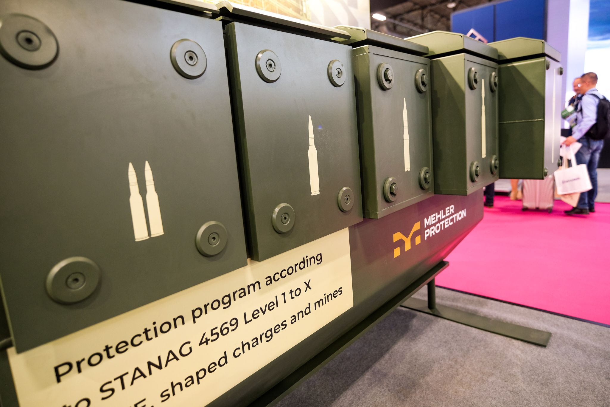
To counter these threats effectively, protective measures are developed according to the well-defined test criteria set out under NATO AEP-55 STANAG 4569. This standardisation agreement defines protection levels for ballistic and mine protection along with resistance to IED strikes. The criteria serve as the basis for the development of modern protection systems.
Threats to military land vehicles
1. Kinetic energy (KE) threats
Conventional ballistic threats from infantry weapons, machine guns or aircraft cannons range from calibres such as 7.62 mm to armour-piercing ammunition such as 30 mm APFSDSs (armour-piercing fin-stabilised discarding sabots).
STANAG 4569 defines protection levels from 1 to 6, which specify the resistance to different projectiles – from small arms to 30 mm calibre.
2. Artillery threats
The NATO standardisation agreement also specifies artillery threats to land vehicles, particularly with regard to protection against fragments resulting from artillery shell detonations. The protection levels according to STANAG 4569 KE are supplemented by corresponding artillery threats known as fragment simulating projectiles (FSPs). These FSPs serve as standardised fragment models in test procedures.
| Level | KE-Threat | Reference Artillery Threat |
| 6 | Weapon: Automatic Cannon, 30 mm Ammunition: APFSDS and AP Distance: 0 m Angle: frontal arc to centreline: ± 30° sides included; elevation 0 |
Artillery 155 mm Estimated range of burst: 10 m Azimuth 360° Elevation: 0 – 90° |
| 5 | Weapon: Automatic Cannon, 25 mm Ammunition: APDS and APFSDS Distance: 0 m Angle: frontal arc to centreline: ± 30° sides included; elevation 0° |
Artillery 155 mm Estimated range of burst: 25 m Azimuth 360° Elevation: 0 – 90° |
| 4 | Weapon: Heavy Machine Gun, 14.5 mm Ammunition: AP Distance: 200 m Angle: azimuth 360°; elevation 0 |
Artillery 155 mm Estimated range of burst: 25 m Azimuth 360° Elevation: 0 – 90° |
| 3 | Weapon: Machine Gun and Sniper rifles, 7.62 mm Ammunition: AP tungsten carbide and AP hard steel core Distance: 30 m Angle: azimuth 360°; elevation 0-30° |
Artillery 155 mm Estimated range of burst: 60 m Azimuth 360° Elevation: 0° – 30° |
| 2 | Weapon: Assault rifles, 7.62 mm Ammunition: AP steel core Distance: 30 m Angle: azimuth 360°; elevation 0-30° |
Artillery 155 mm Estimated range of burst: 80 m Azimuth 360° Elevation: 0° – 22° |
| 1 | Weapon: Assault rifles, 7.62 and 5.56 mm Ammunition: Ball Distance: 30 m Angle: azimuth 360°; elevation 0-30° |
Artillery 155 mm Estimated range of burst: 100 m Azimuth 360° Elevation: 0° -18° |
3. Shaped charge threats
Shaped charges, such as those used in anti-tank guided weapons (ATGMs) and rocket-propelled grenades (RPGs), pose a particularly dangerous threat as they can penetrate conventional armour through focused impact. The RPG-7’s warhead, for instance, forms a penetration element that achieves high speeds and penetration power upon launch. These shoulder-launched systems are widely used and relatively inexpensive to obtain.
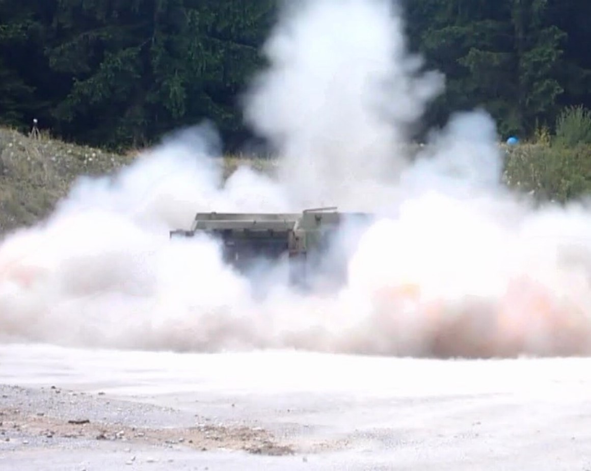
4. Improvised explosive devices (IEDs) and mines
Improvised explosive devices (IEDs) and landmines are common threats in asymmetric conflicts and have destroyed many vehicles in recent decades. They are usually designed to deliver a powerful explosive force and target vehicle chassis.
STANAG 4569 levels 1–4 specify protection against the detonation of mines under chains or wheels and under the vehicle fuselage.
| Level | Grenade and Blast Mine Threat | ||
| 4 | 4b | Mine Explosion under belly | 10 kg (explosive mass) Blast AT Mine |
| 4a | Mine Explosion pressure activated under any wheel or track location | ||
| 3 | 3b | Mine Explosion under belly | 8 kg (explosive mass) Blast AT Mine |
| 3a | Mine Explosion pressure activated under any wheel or track location | ||
| 2 | 2b | Mine Explosion under belly | 6 kg (explosive mass) Blast AT Mine |
| 2a | Mine Explosion pressure activated under any wheel or track location | ||
| 1 | Hand grenades, unexploded artillery fragmenting sub-munitions, and other small anti personnel explosive devices detonated anywhere under the vehicle | ||
5. Top-attack threats: loitering munition, bomblets and drones
A new, increasingly dangerous threat comes from weapons that attack a target from above – an area that is inadequately protected by many conventional armour systems.
- Manoeuvrable kamikaze drones with armour-piercing warheads constitute loitering munition.
- Cluster munitions’ bomblets can eject armour-piercing submunitions across a wider area.
- Drones with explosive charges or guided weapons are a flexible threat and can be controlled remotely.

Special features of protection systems for land vehicles
1. Combination of passive, reactive and active protection systems
Modern vehicles often use a combination of passive armour, reactive systems and active protection mechanisms to ensure maximum protection while keeping weight to a minimum.
- Passive protection systems include composite armour, auxiliary armour and energy-absorbing materials. The major advantage of passive systems is that they always function independently of any sensor technology or operating conditions, even when incurring a high rate of fire. The system weight generally increases concurrent to the protection level. However, the use of suitable materials such as ceramics and fibre composites can massively decrease the weight compared to pure armoured steel solutions. The system can also be configured in a polyvalent manner such that it protects against different threats simultaneously, e.g. shaped charge protection with integrated KE and artillery protection.
- Reactive armour (ERA) destroys incoming shaped charge projectiles or large calibre KE projectiles by generating a counter-explosion. This saves weight compared to purely passive solutions. Reactive protection is typically designed to be used in conjunction with light passive protection to ensure safety. However, these systems are not suitable for all vehicles or use scenarios, as triggering the reactive modules can lead to fragmentation effects in the immediate vicinity – and therefore a potential risk of collateral damage. ERA can also be triggered by small-calibre attacks, leaving it depleted when the time comes to serve its actual purpose. This significantly reduces the protection afforded to the vehicle.
NERA (non-explosive reactive armour) is a special type of reactive system. This functions without explosives by generating a physically reactive effect to nullify the projectile. As a result, NERA systems are more likely to be part of passive protection solutions, as they do not have the disadvantages of ERA systems but are nevertheless significantly heavier.
- Active protection systems (APS) such as Trophy or Iron Fist detect and neutralise incoming threats through targeted countermeasures. They are particularly effective against slower, approaching guided missiles such as RPGs or ATGMs and rely on hard-kill mechanisms such as interceptors. Their effectiveness against KE projectiles such as APFSDS ammunition has so far been limited, as this kind of projectile approaches at high speed and is difficult to detect. In addition, APS significantly increases the technical complexity of the vehicle, as it requires sophisticated sensors and rapid response times. As a result, integration is expensive and presents challenges in terms of maintenance, power supply and avoidance of collateral damage, especially in the vicinity of friendly troops or in built-up areas.
Due to the different advantages and disadvantages of the systems, it is necessary to weigh up each individual case based on a variety of factors to determine which type of protection system is suitable or whether a combination of systems is required.
2. Modular passive protection systems
Passive systems offer the widest range of protection solutions, as they can be used against all kinds of threats. In general, a distinction is made between different types of passive protective structures, which together function as a modular overall solution that meets the required protection requirements.
Stand-alone-armour
An example of a stand-alone armour is a vehicle hull made of armoured steel, which on its own provides basic protection against KE and artillery shrapnel.
Add-on-armour
Add-on armour can be installed as an upgrade to the vehicle’s basic protection to increase its protection level, e.g. from KE level 1 to KE level 3. Moreover, some add-on armour is designed to protect specifically against shaped charges or as systems in the roof area, e.g. against bomblets.
Spall Liners
Spall liners are fibre composite systems mounted in the interior of the vehicle to protect against penetrating fragments, e.g. due to armour material flying off from the vehicle shell. These liners can be designed as redundant systems to increase occupant protection or as part of the overall design concept.
Mine protection systems
V-shaped vehicle underbodies and energy-absorbing materials are proven protective measures against mine and IED threats. However, as the protection level increases, so does the degree of complexity of the mine protection solution, as a comprehensive system design is required to ensure occupant protection. Shock-absorbing systems, dampers and decouplings are used to achieve this.
Distance-sensitive systems
Mesh or lattice solutions are used to protect military vehicles from armour-piercing ammunition. These systems trigger the detonation of a warhead at a defined distance from the vehicle hull, which reduces the energy of the charge. They offer a lightweight, cost-effective and retrofittable protective measure, but their effectiveness is severely limited.
Vulnerability analyses to identify critical vulnerabilities
An effective protection strategy starts by conducting a comprehensive vulnerability analysis to identify critical vulnerabilities. The following factors are taken into account:
1. Threat analysis: what types of threats are expected on this specific mission?
A threat analysis includes clarifying imprecise or incomplete requirements as well as providing information on the essential background to mission-related threats, their impact and the required testing methods. Probability analyses can be used to evaluate needs and priorities so a prioritised design can be carried out in accordance with the risk situation.
2. Systematic weak point analysis: which areas of the vehicle are particularly vulnerable?
The first step of a system analysis is to identify integration options according to protection requirements. Weaknesses can then be identified and measures taken to optimise them. Particularly vulnerable components are given special consideration, with occupant protection always having the highest priority. This step serves as the basis for the subsequent conceptual design, in particular when it comes to upgrade projects for existing systems.
Areas that are especially critical for land vehicles are:
- Crew compartment: a maximum level of protection is sought to maximise the occupants’ chance of survival.
- Vehicle underbody: particularly vulnerable to mines and IEDs. Here, too, the effect on the occupants plays a major role.
- Tower and sensors: a failure can significantly reduce the combat strength of the vehicle. Modern vehicles are also equipped with a variety of optronics systems, which serve as the eyes and ears of the platform.
- Vehicle roof: for weight reasons, the vehicle roof generally only has minimal protection; this is not adequate against serious threats, such as a shaped charge dropped by a drone. This threat was not considered in past designs and needs to be reassessed.
3. Protection system design
An optimal protection concept is developed based on previous analyses and/or defined requirements that takes into account the threat situation, integrative characteristics as well as weight and environmental requirements. This is the stage of development where it is decided which type of additional armour, mine protection etc. will be used and whether a combination of systems is expedient (e.g. passive and reactive). In addition, each subsystem can be designed in a way that optimises its specific use in an individual vehicle.
4. Final validation
Both the individual systems and the vehicle as a whole must demonstrate their performance in accordance with the test criteria of AEP 55 STANAG 4569. Once complete, the system – with all its subsystems – is qualified.
Summary
Ballistic protection for military land vehicles is a complex challenge as the threat situation is constantly evolving. While conventional KE threats and shaped charges continue to be dangerous, modern forms of attack such as IEDs, mines and above all top-attack weapons pose a growing threat.
Standardisation according to AEP-55 STANAG 4569 allows protection systems to be tailored to specific threat scenarios. The combination of passive protection, reactive armour, active protection systems and drone defence is crucial to provide vehicles and crews with maximum protection on modern battlefields.
Only by conducting thorough vulnerability analyses and adapting protective measures in a flexible manner can military land vehicles continue to fulfil their role as protected carriers of firepower and mobility in the future. There is an urgent need to develop new protection concepts in the field of drone defence, in particular.
Mehler Protection is therefore highly innovation-driven and focuses strongly on research and technology development. For example, the M-RACC product family has already been supplemented by the PROTEC3D product family to protect against conventional threats such as KE ammunition, shaped charges, mines, bomblets and IEDs. PROTEC3D uses 3D printing technology with armoured steel to protect vehicle elements, e.g. optronics systems. The issue of drone defence is currently at the heart of developments.
Images and graphics: Mehler Protection, Mehler Engineered Defence GmbH (All rights reserved, 2025)